Your Cart is Empty


Overhead Crane Capacity Upgrade: A Structural Feasibility Guide for Plant Engineers

Two in three middle-market manufacturers (companies in the $10M to $1B revenue range) surveyed byFirst National Capital plan to raise equipment investment in 2026, with a median planned spend of $4.2 million per company.
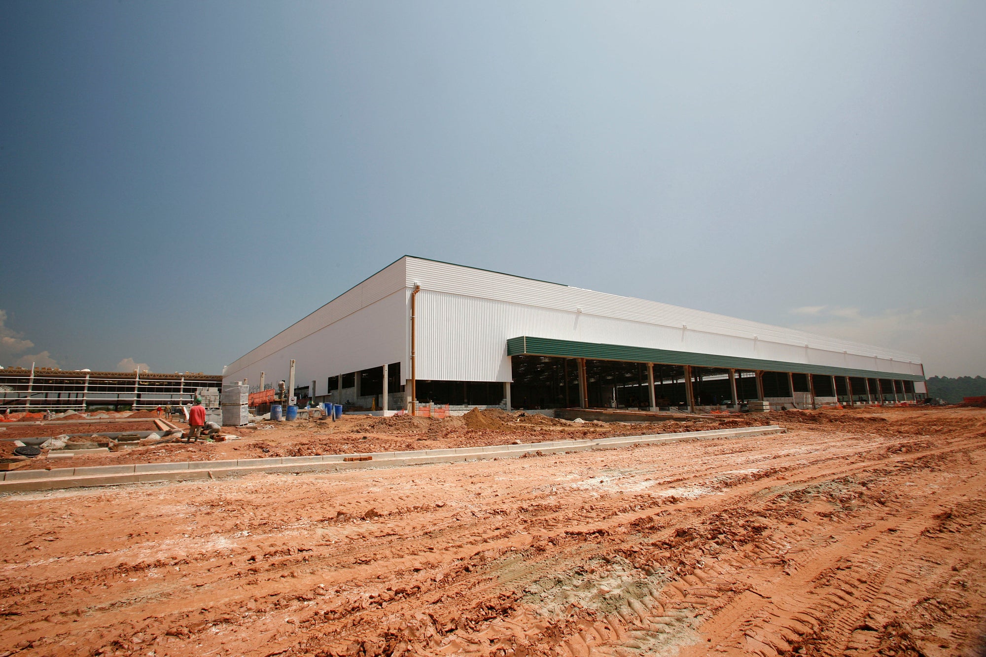
TheISM 2026 forecast projects U.S. manufacturing capital spending up roughly 3% in 2026 on top of a 3.5% gain in 2025, with the largestreshoring announcements of 2024 concentrated in computer and electronics and electrical equipment, including EV batteries and solar. These are heavy-material sectors, and much of that capital is landing in existing buildings with bridge cranes sized for the previous production mix. That makes the capacity-upgrade decision a 2026 priority for plant engineering and procurement.
A capacity upgrade is a structural-engineering decision before it is a crane-mechanical one. Hoists, trolleys, and end trucks can be replaced in days; runway beams, columns, bracing, and foundations cannot.OSHA 1910.179(b)(3) requires modifications and the supporting structure to be checked thoroughly for the new rated load by a qualified engineer or the equipment manufacturer before the crane is rerated, so the feasibility study runs from the building down to the crane.
Table of Contents
-
The Building Decides First
-
Four Reinforcement Strategies
-
When Derating Wins
-
Upgrade vs Replacement
-
Closing the Compliance Loop
-
The Pre-Engagement Checklist
-
How HOJ Approaches Upgrades
The Building Decides First
AISC Design Guide 7 Industrial Building Design (3rd Edition, 2019), Chapter 14, controls crane runway design in U.S. practice. The feasibility study has four pieces.
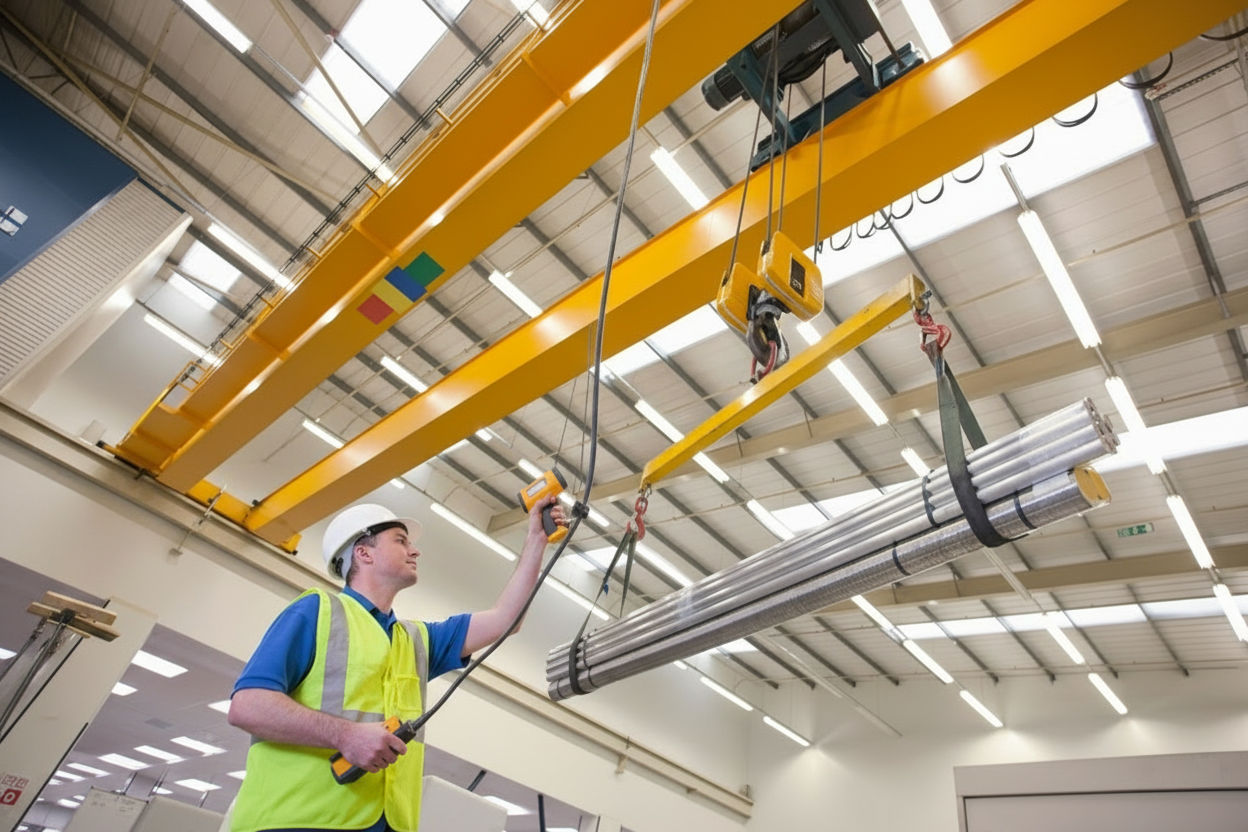
Runway Beams and Impact
Crane runways are the steel rails the bridge rolls on, and they're designed to bend only a tiny amount under load. Vertical deflection (how much the beam sags downward) is commonly limited to L/600 to L/1000 of the span depending on duty class, meaning a 60-foot beam can sag no more than about an inch. Lateral deflection (side-to-side flex) is commonly limited to L/400. These ratios exist because too much flex causes wheel binding, accelerated wear, and eventual structural fatigue.
Here is the catch: when engineers calculate whether a beam meets these limits, they do not just use the static weight of the lifted load. They use a higher number that accounts for the dynamic forces of lifting, accelerating, and stopping.ASCE 7 impact factors set a 25% vertical impact factor for cab-operated and remotely operated cranes and 10% for pendant-operated cranes, meaning the runway must be designed to handle wheel loads 25% (or 10%) heavier than the rated capacity.CMAA Specification 70-2025 adds a hoist load factor between 15% and 50%, scaled to how fast the hoist lifts. Faster hoists hit the beam harder.
What this means in practice: increasing a cab-operated crane's rated capacity from 50 tons to 75 tons is not a 75-ton problem for the runway, it is a 75 × 1.25 = 93.75-ton wheel-load problem. If the original runway was sized for the 50-ton crane with its impact factor, the new wheel loads may exceed what the beams and columns were built to handle.
Fatigue is the second governing concern. Fatigue is the cumulative damage steel accumulates from repeated load cycles, even when no single lift exceeds capacity. Think of it like bending a paperclip back and forth until it snaps. The AISC Engineering Journal'sfatigue design provisions for crane runway girders flag fatigue as a top issue in crane buildings, and a Class C crane (moderate duty) pushed to Class D throughput (heavy duty) carries new fatigue assumptions the existing girder may not satisfy. More lifts per shift means more cycles, which means the runway designed for the original service class may fatigue out years earlier than expected.
Columns, Connections, Foundations
The columns are the vertical steel members that support the runway beams and transfer everything they carry down to the foundation. Columns must be verified for three different kinds of force under the new wheel loads:axial force (straight-down compression from the weight pushing into the column),bending moment (sideways force trying to bend the column like a lever), andshear (force trying to slice the column horizontally, like scissors). Each one is calculated separately because steel resists each one differently.
Beam-to-column connections (the welded or bolted joints where horizontal beams meet vertical columns) in older buildings often need reinforcement. This typically means addingstiffeners (vertical plates welded inside the connection to prevent the column web from buckling),gussets (triangular plates that distribute force across a wider area of the joint), orstrengthening plates (additional steel welded onto existing members to increase their cross-section). Lateral bracing, the diagonal steel that keeps the structure from racking sideways, must also resist new forces fromskew (when the bridge crabs sideways instead of running straight),trolley acceleration (sideways jolts as the trolley starts and stops along the bridge), andaccidental contact (impact loads from hitting end stops or other equipment). This is where reinforcement work concentrates, and so do cost overruns, because every connection that needs upgrading means cutting, welding, and inspection on a structure that may also need to stay partially operational during the work.
A foundation survey verifies that footings (the concrete pads under each column) and the slab carry the new wheel reactions. Demand at the footing changes even when the column above looks identical, because higher loads at the top of the column translate into higher pressure pushing into the soil below. A foundation that was adequate for the original crane may now be undersized, and discovering that after the columns are reinforced is the worst possible sequence.
Runway Alignment Tolerances
Crane runways have to be straight, level, and parallel within very tight tolerances, because the bridge wheels ride on two rails that must stay in near-perfect alignment with each other. If one rail drifts even a fraction of an inch out of position, the bridge starts to "crab" (run at a slight angle instead of straight), which forces the wheels to grind sideways against the rail flanges and adds stress the runway was never designed to absorb.
There are two main alignment standards.CMAA 70 Table 1.4.2-1 sets a flat ±1/4 inch span variation (meaning the distance between the two rails can vary by no more than a quarter inch anywhere along the runway), with overall straightness and elevation each within ±3/8 inch (the rails cannot bow sideways or wave up and down by more than 3/8 inch over the full length).AIST Technical Report 13, which steel mills and other heavy-duty users follow, sets stricter tolerances: 3/16 inch up to 50 ft of runway, 1/4 inch from 50 to 100 ft, and 3/8 inch above 100 ft. AIST is tighter because heavy-duty cranes run more cycles per shift and any misalignment compounds faster.
Here is why it matters for capacity increases: a runway already at the edge of these limits will not accept additional wheel load. The existing crane is already using up the structural margin that misalignment eats into, and adding a heavier crane only makes the binding and side-thrust worse. This is why a3D laser-based runway survey (a high-precision scan that maps every inch of both rails in three dimensions) is a standard precondition before any capacity increase.Rail-to-web misalignment (the rail sitting slightly off-center on the supporting beam below it) can already be reducing structural capacity by forcing wheel loads into the beam at an angle rather than straight down. Without the survey, you are budgeting reinforcement work blind.
Four Reinforcement Strategies
When the review identifies a deficit, four strategies cover most projects. The 1998 Ellifritt and Lue paper onchannel cap reinforcement, "Design of Crane Runway Beam with Channel," is the analytical basis for the most common method.
|
Reinforcement Method |
Scope |
Typical Downtime |
Engineering Complexity |
|
Cap channel on top flange |
Resists lateral-torsional buckling, gains section modulus |
1 to 2 weeks per bay |
Moderate |
|
Bottom-flange cover plate |
Adds section modulus where the top flange already has a cap |
1 to 3 weeks per bay |
Moderate to high |
|
Column stiffening with welded angles and grouted base plate |
Adds axial and bending capacity at the column base |
2 to 4 weeks per column |
High |
|
Supplemental parallel beam |
New girder runs parallel to existing, shares load |
3 to 6 weeks |
High; may require new column line |
The cap channel is the workhorse. The supplemental parallel beam is reserved for projects where local reinforcement cannot close the demand gap. A pre-engagement structural model identifies the right combination, and the cost, before site work begins.
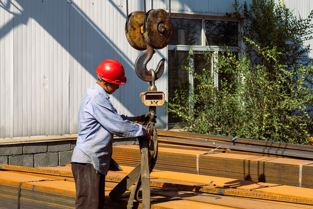
When Derating Wins
The engineering answer is sometimes the opposite of an upgrade. When reinforcement is impossible or uneconomical, a crane can be operated at a lower capacity with a documented rerate.OSHA rerating provisions at 1910.179(b)(3) permit modification and rerating provided the equipment and supporting structure are checked by a qualified engineer or the manufacturer. Operating a 50-ton crane at 30 tons with a new capacity plate and a 125% load test at the new rating is a fully compliant outcome when production has shifted to lighter loads or when fatigue limits justify a lower service classification.
Upgrade vs Replacement
Upgrade wins when local reinforcement closes the demand gap, the crane is under 15 to 20 years old, and the production layout is staying. Replacement wins when the crane is at fatigue end-of-life, the production layout is changing (new span, new runway), or column-connection reinforcement is uneconomical. AISC Design Guide 7 emphasizes that structural cost dominates the budget once columns, foundations, or bracing are touched. Run the structural review before purchase orders are issued, not after.
Closing the Compliance Loop
A capacity upgrade is not finished until three boxes are checked. A qualified engineer or the OEM signs off the new rated load per OSHA 1910.179(b)(3) and theASME B30.2 standard (B30.2-2022), the prevailing safety standard for top-running bridge cranes. The new rating is plainly marked on each side of the crane and on each hoisting unit per 1910.179(b)(5). The crane passes arated load test at no more than 125% of the new rated load per 1910.179(k)(2), with a written report on file; ASME B30.2 reinforces the same 125% ceiling unless the manufacturer specifies otherwise. CMAA 70 and 74 (2025 editions) govern current uprating work, and CMAA 70-2025 added a wind-area rule that surfaces during feasibility for outdoor or open-bay cranes.
The Pre-Engagement Checklist
Bring the following to the first meeting with the third-party Professional Engineer:
-
Existing capacity plate and OEM nameplate data
-
Original drawings: bridge, runway, columns, and foundation
-
Current and intended CMAA duty class (Class C at up to 10 lifts per hour is a different fatigue problem than Class E at 20-plus lifts per hour at or near rated capacity)
-
Documentedrunway alignment survey within the last 24 months
-
Current ASME B30.2 inspection records
-
Building structural drawings or as-built
-
Intended new lift weights and lift-cycle frequency
-
Outdoor or indoor classification, which triggers the CMAA 70-2025 wind-area check
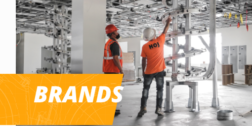
How HOJ Approaches Upgrades
HOJ Innovations has been working onoverhead bridge cranes for over 60 years. A capacity upgrade starts with a structural review of the runway, the columns, and the foundations to determine how much load the existing structure can carry. Contact HOJ to discuss what's right for your facility.